tctuvan

New Member

Hướng dẫn cài đặt Unigraphic NX 8.0


Về cách cài đặt thì hoàn toàn giống với NX7.5 . Nghĩa là cần cài cả UGSLicensing trong Host server để kích hoạt và Start Server thành công . Khi chạy file Launch của NX8.0 thì phần đánh dấu trong hình là phần chúng ta cần cài đặt vào ổ cứng :

Đầu tiên càiNX trước (hay UGSLicensing trước cũng vẫn được) :

setup nx8

Click Next và chọn Typical để cài đặt đầy đủ các Feature của NX :

Chọn vị trí cài đặt trên ổ cứng :

setup nx8

Ở bước này source cài sẽ tự động điền tên của PC vào nên các bạn cứ để như mặc định :

setup nx8

Chọn ngôn ngữ , các bạn cứ để English như mặc định và click Next :

setup nx8

Bước này source cài sẽ hiển thị lại một lần nữa những tùy chọn mà bạn đã chọn khi cài đặt ở các bước trước , nếu không có gì cần thay đổi thì các bạn cứ nhấn càiđể bắt đầu cài đặt :

setup nx8

Copy các Folder DRAFTINGPLUS, NXCAE_EXTRAS, NXNASTRAN, NXPLOT and UGII chép đè vào các Folder tương ứng theo đường dẫn C:\Program Files\Siemens\NX 8.0 (ổ C là ổ đã chọn để cài đặt NX)
Đến đây thì chúng ta đã hoàn thành phần cài đặt NX , tiếp theo chúng ta cần cài đặt thêm License Server để kích hoạt Server của Host Server

setup nx8

Click Next và chọn vị trí cài đặt (nên để như mặc định)

setup nx8

Click Browser và chỉ đường dẫn tới file NX8.0.lic trên ổ cứng (file này nằm trong folder UGSLicensing của Cr-ack
Chú ý : đường dẫn trong hình là nơi mình thường lưu file Lic của NX khi cài đặt để dễ quản lý nên vị trí này không phải là bắt buộc , các bạn có thể chứa file Lic ở bất kỳ nơi nào nhưng khi đã cài rồi thì không được xóa file Lic hay di chuyển đi nơi khác , vì nó sẽ làm cho UGSLicensing mà bạn đã cài đặt mất đi đường dẫn tới file Lic này . Vì vậy đây là lý do mình để file Lic này ở trong nơi mình cài đặt NX trên ổ cứng để tránh bị thay đổi hay xóa mất mà dẫn đến lổi và không thể khởi động được NX

setup nx8

Chạy file lmtools.exe theo đường dẫn C:\Program Files\UGS\UGSLicensing (ổ C là ổ cài đặt NX) . Chuyển qua Tab Start/Stop/Reread và click Stop Server như hình

setup nx8

Copy file ugslmd.exe nằm trong Folder UGSLicensing của Cr-ack (file này nằm chung thư mục với file Lic) chép đè lên file tương ứng theo đường dẫn C:\Program Files\UGS\UGSLicensing (ổ C là ổ đà chọn để cài đặt NX).
Cuối cùng chúng ta chạy lại file lmtools.exe . Ở Tab Start/Stop/Reread , đánh dấu vào tùy chọn Force Server Shutdown , sau đó click vào Start Server để bắt đầu chạy Server , nếu nó hiện thông báo phía dưới là Server Start Successful là chúng ta đã chạy Server và Cr-ack NX8.0 thành công . Giờ thì chúng ta chỉ việc chạy NX và khám phá những chức năng mới của NX8.0 thôi
 

tctuvan

New Member
Advantages of cad

1.Definition.

Cad – computer aided design: These are softwares that people can use for make plans, drawings, edit drawings,… by computer.Before the age of computers, drawings were drafted by hand. CAD is more efficient because the software records lines as vectors based on mathematical equations. Portions of a drawing can be twisted, stretched, or moved. The picture as a whole will automatically adjust.
2. Advantages of CAD.
+ Create and edit the drawing easy:
+ Switch between two-dimensional (2D) and three-dimensional (3D) views.
+ Zoom in and out for close-up and distant views.
+ Rotate images to view them from different perspectives.
+ Change the scale of images: When one value changes, related values are automatically adjusted.
+ Manipulate the shape of images: Changing one portion of an image automatically changes the entire picture.
+ Increase accuracy.
+ Save and sent drawing easy.
+ Can analyse, calculation durability of sample –> design down time


History of unigraphics


NX, also known as NX Unigraphics or usually just U-G, is an advanced CAD/CAM/CAE software package developed by Siemens PLM Software.
NX is one of the world’s most advanced and tightly integrated CAD/CAM/CAE product development solutions. Spanning the entire range of product development, NX delivers immense value to enterprises of all sizes. It simplifies complex product designs, thus speeding up the process of introducing products to the market.
The NX software integrates knowledge-based principles, industrial design, geometric modeling,advanced analysis, graphic simulation, and concurrent engineering. The software has powerful hybrid modeling capabilities by integrating constraint-based feature modeling and explicit geometric modeling. In addition to modeling standard geometry parts, it allows the user to design complex free-form shapes such as airfoils and manifolds. It also merges solid and surface modeling techniques into one powerful tool set.
+ It is used, among other tasks, for:
Design (parametric and direct solid/surface modelling)
Engineering analysis (static, dynamic, electro-magnetic, thermal, using the Finite Element Method, and fluid using the finite volume method).
Manufacturing finished design by using included machining modules.
NX is a direct competitor to Creo Elements/Pro, CATIA, SolidWorks and Autodesk Inventor.
HISTORY:
1969: UNIAPT was released by a software company then called United Computing, UNIAPT was one of the world’s first end-user CAM products.
1973: The company purchased the Automated Drafting and Machining (ADAM) software code from MGS in 1973. The code became a foundation for a product called UNI-GRAPHICS, later sold commercially as Unigraphics in 1975.
1976 McDonnell Douglas Aircraft buys Unigraphics.
1981: Unigraphics was released, marking the group’s first true 3D modeling hardware and software offering.
1991: During a period of financial difficulties McDonnell Douglas sells Unigraphics to EDS which at that time is owned by General Motors.Unigraphics becomes GM’s corporate CAD system.
1992: Over 21,000 seats of Unigraphics are being used worldwide.
1996: Unigraphics V11.0 is released. Added Industrial Design and Modeling enhancements including Bridge Surface, Curvature Analysis for Curve and Surfaces, Face Blends, Variable Offset Surface, etc. In the area of Assembly Modeling the new capabilities included Component Filters, Faceted Representations, Clearance Analysis between multiple Components, etc. Also this release included a fully integrated Spreadsheet linked to Feature-Based Modeling.
2002 First release of the new “Next Generation” phiên bản of Unigraphics and I-deas, called NX. This will eventually bring the functionality and capabilities of both Unigraphics and I-DEAS together into a single consolidated product.
2007 Introduction of Synchronous Technology in NX 5.
A complete history exists on the Unigraphics Virtual Museum.
NX 7.5 is the current release.


Cách sử dụng chuột


The mouse is very important and necessary with designer. In Unigraphic-nx mouse can use to move part, zoom, pan, rotate, choose part,…There are three mouse configurations in common use.

mouse of computer

On a two-button mouse, use the left and right buttons together when you need the middle button.
In this post, we will review about three-button mouse.
Mouse controls
How to do
Rotate
+ Press and hold the middle mouse button and drag around the screen to view
Pan
+ Press and hold both the middle button and right mouse button simultaneously and drag + Press and hold button on the keyboard and press and drag the middle mouse button to pan
Zoom
+ Press and hold both the left mouse button and middle button + Press and hold button on the keyboard and then press and drag the middle mouse button + Scroll up and down the middle button
+ Right mouse button: Display shortcut menu with various functions. Also display action information for currently selected objects.
 

tctuvan

New Member
Unigraphic – nx datum plane review

Unigraphic – nx datum plane review


Datum plane is a planar reference feature. It can use as aids to create other features, such as swept bodies and features at angles to the faces of target solids. Datum plane can be relative or fixed.
1. Datum plane type

unigraphic – nx datum plane type

2. Datum plane options.

unigraphic – nx datum plane options

3.Applications for datum planes
•To define a sketch plane.
• To serve as the planar placement face for the creation of features with predefined shapes, such as holes.
• As a target edge for positioning features such as holes.
• For the mirror plane when using the Mirror Body and Mirror Featue commands.
• To define the start or end limits when creating extruded and revolved features.
• To trim a body.
• To define positioning constraints in assemblies.
• To Giúp define a relative datum axis.
 

tctuvan

New Member
How to create a datum plane

In this tutorial, i will show how to create a datum plane in unigraphic-nx with at distance, at angle, bisector.
To open datum plane box, you can select : Insert→Datum/Point→Datum Plane.
unigraphic – nx open datum plane box

Or select datum plane button in Feature bar.

unigraphic – nx datum plane button

After select datum plane button, the datum plane box below will show:

unigraphic – nx datum plane type

1. How to create a datum plane with at distance.

unigraphic – nx Create datum plane with at distance

Step1: Select At distance in type box.
Step 2: Select plane, face that you want to create parallel plane.
Step3: In put distance.
Step 4: Number of planes
If you want to change direction of plane. Click Reverse dirsction at offset table.
Step5: Click Apply –> Ok to finish your works.
2. How to create a datum plane with at angle.

unigraphic – nx create datum plane with at angle

Step1: Select At angle in type box.
Step2: Select plane, face that use as a reference for measuring the angle.
Step 3: Select a linear curve, edge, or datum axis, that defines the angle’s axis of rotation.
Step4: Select angle at angle table. We have three type.
+ Perpendicular: Create a plane that perpendicular with plane you select in step 2.
+ Parallel: Create a plane that parallel with plane you select in step 2.
+ Value: Input angle to angle box.
Step 5: Use offset option if you want to move parallel plane.
Step 6: Click apply –> OK to finish .
3. How to create a datum plane with bisector.

unigraphic – nx create datum plane with Bisector

Step1: Select Bisector at type box.
Step 2: Select the first face, plane.
Step 3: Select the second face, plane (The second face do not need parallel with the first face, plane.)
Step 4: Use offset option if you want to create parallel plane.
Step 5: Click Apply –> Ok to finish.
 

tctuvan

New Member
How to use quick trim

In sketch, quick trim use to trims a curve to closest intersection or to a selected boundary.
1. How to open quick trim
+ On the Sketch Curve toolbar, click Quick Trim

NX-Sketch Curve toolbar – Quick Trim

+ Select Edit→Curve –> Quick Trim.

NX-Edit – Curve – Quick Trim

After you select quick trim button the box below will show.

NX- Quick Trim box

+ If you select Boundary curve, it will divide other curves to 2 part that you can trim but you can’t trim the curves are boundary curve. . But I think, you don’t need select it.
+ Curve to trim: Select the curve that you want to trim.
2. The example about use quick trim.
+ Quick trim with boundary curve.

NX- example quick trim with boundary curve

In this picture: Orange curve is Boundary curve, Red curve is curve that want to trim.
+ Quick trim don’t use boundary curve

NX- example quick trim don’t use boundary curve

In this picture: Red curve is curve that want to trim.
+ You can trim multiple curves with a left mouse press-and-drag operation.

NX- example quick trim with drag operation

In this picture: Orange curve is drag operation.
3. Quick Trim constraints.
When the Create Inferred Constraints option is active, the Sketcher infers appropriate constraints after a trim operation.
ConstraintTrim Operation
ConcentricAn arc in the middle.
CoincidentIntersecting lines to an intersection point.
Point on CurveA curve to a boundary curve.
CollinearA line in the middle
Equal RadiusAn arc in the middle.
TangentA curve at the tangent point of a boundary curve.
See video below for more tutorial.


tctuvan

New Member
How to edit object display color

In your work, some times you need to modify the layer, color, front, grid count,…of the parts, with beginner may be you don’t know so i write this tutorial. To modify the color, the first you can press CTLR + J in your keyboard or click Edit Object Display button.

unigraphics – nx Edit Object Display Icon

Step 2. The first, select objects (face, solid body, sheet, datum plane,…) that you want to modify, then click OK button.

unigraphics – nx edit object display select obj

Step 3 . After you click color label–> OK–> OK to finish your work.

unigraphics – nx edit object display select color

After you click Ok button, please see your result. If you don’t want to your modify, press Ctrl + Z on your keyboard.

unigraphics – nx edit object display result

See this video for all process.


tctuvan

New Member
How to design a bolt

Thiết kế cái bu lông ốc vít bằng Unigraphic

This tutorial will show how to design a bolt in unigraphics – nx 8. To design bolt we use three commands: Extrude, Revolve, Threads.

nx tutorial design bolt

See this video for more tutorial.


tctuvan

New Member
How to create hole features

How to create hole features


Thiết kế một hố bằng unigraphic

When design products, some times we need create holes. To support designer, in unigraphics – nx we can use the Hole command to create simple, counterbored, and countersunk, tapered holes in a solid body. Holes features support automated feature identification in the Holemaking application.
1. Hole types.

hole types

2. How to create a hole.
step 1. Open Hole feature box. We have 2 way for opening:
+ From the menu bar, choose Insert→Design Feature→Hole.
+ On the Feature Operation toolbar, click Hole.

unigraphics – nx – hole feature

Step 2: Select type: General hole.
step 3: Select the Type: Simple, Counterbore, Countersink or tapered.
Step 4: Select center point of hole, a planar placement face.
Step 5: Select direction of hole
Step 6: Input dimension of hole.
Step 7: Select Boolean.
Step 8: Click Apply –> OK
3. See this video for more tutorial.


tctuvan

New Member
How to export UG file to iges, xt file

Some times, you need to export unigraphics -nx file to iges or xt file because your friend use other cad software or old phiên bản of nx.
This tutorial below is step by step instruction to export unigraphics – NX 8 file to *.iges file for other cad cam software and *.XT for old phiên bản of nx.


unigraphics – nx 8 tutorial export file type

See video below for full tutorial.


tctuvan

New Member
How to use quick extend

This tutorial i will show how to use quick extend in unigraphics – nx. Quick extend use to extends a curve to a nearby curve or to a selected boundary. We have two ways to access the Quick Extend command:
+ Select quick extend on the sketch cuver toolbar.

unigraphics – nx how to access quick extend command

+ Choose Edit–> Curve –> Quick extend.
After access quick extend command we have two type. Select Boundary or don’t select boundary. If you don’t select a bounary, all curve are boundaries.
Note: You can select multiple curve to extend with a left mouse press-and-drag operation.
See this video belor for more how to use quick extend.


tctuvan

New Member
Thiết kế 1 chiếc ghế sử dụng UniGraphic

how to design a chair


This step by step tutorial about design a chair in unigraphics-nx. In this tutorial we use three commands: extrude, round, shell.

nx tutorial design the chair

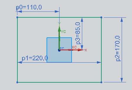
Step 1: In xOy plane, drawing a rectang with dimension: 220×170

nx tutorial how to design a chair step 1

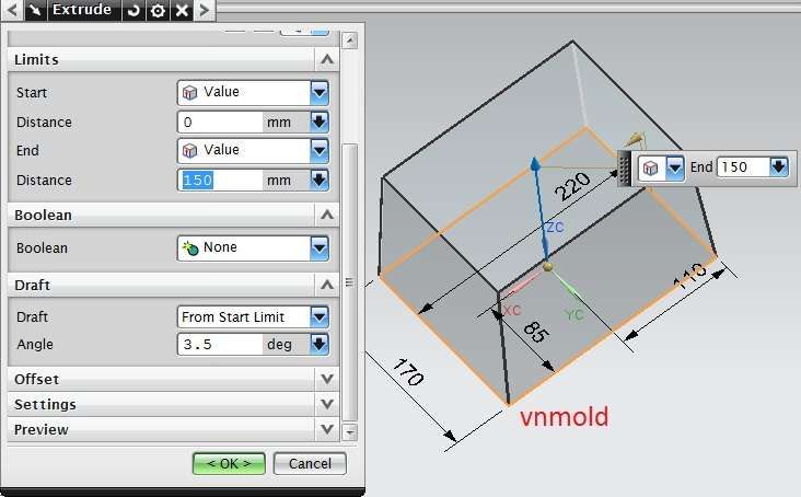
Step 2: Extrude rectang in step 1 with distance 150, draft 3.5

nx tutorial how to design a chair step 2

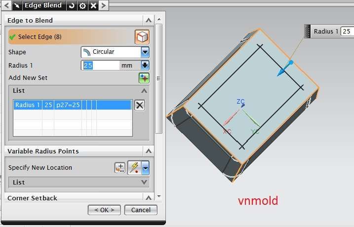
Step 3: Round edge of chair with R=25.

nx tutorial how to design a chair step 3

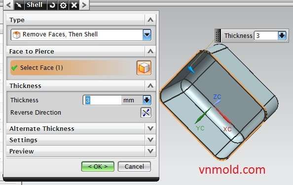
Step 4: Use sell to make thickness of chair.

nx tutorial how to design a chair step 4

Step 5: In xOz plane, drawing a sketcher same picture.

nx tutorial how to design a chair step 5

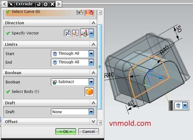
Step 6: Use extrude to cut the box.

nx tutorial how to design a chair step 6

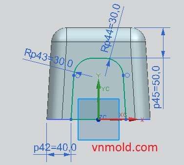
Step 7: In yOz plane, drawing a sketcher same picture.

nx tutorial how to design a chair step 7

Step 8: Use extrude to cut the box same step 6 and see result.

See this video below for more tutorial.
 

tctuvan

New Member
how to get shortcut key

Cách tạo nút tắt trong unigraphic

how to get shortcut key


This post is step by step about how to setting shortcut key in unigraphics-nx.
The first, Select : Tools–> Cuztomize –> keyboard.

nx customize

After you click keyboard the box below will show.

nx setup shorcut key

1: Categories of commands.
2: Select command that you want to get shortcut key.
3: Local to input shortkey.
4. Select Assign.
6. Click report if you want to see all shortcut key of unigraphics-nx.
See video below for more information


tctuvan

New Member

How to use chamfer command


In unigraphics – nx, chamfer command use to chamfers sharp edges between faces. The faces, soild body can attach or subtract when you use chamfer command.
To do chamfer command, you can open it from:
+ On the Feature Operation toolbar, click Chamfer.

unigraphics – nx chamfer command

+ Select: Insert→Detail Feature→Chamfer.
After you select chamfer button, the chamfer option below will show:

unigraphics – nx chamfer command options

Step 1: Select one or more edges .
Step 2: Select cross section. In cross section we have three options
+ Symmetric: use it if you want to chamfer with distance d1=d2.
+ Asymmetric: use it if you want to chamfer with distance d1 # d2.
+ Offset and Angle: use it if you want to chamfer with distance d1 and angle .
Step 3: Input distance, angle that you want to use.
Step 4: Use reverse direction if you want to change direction.
Step 5: In the Settings group, you can select Offset Edges along Faces or Offset Faces and Trim.
Step 6: Click apply –> OK to finish
See video below for more tutorial.


tctuvan

New Member
How to design circular stair

How to design circular stair


Thiết kế cầu thang xoắn bằng unigraphic

This tutorial will how how to design circular stair in unigraphics-nx. To design it, we use these command below.
+ Extrude.
+ Helix.
+ Pattenrn feature.
+ Make spile line with through points
+ Make a plane with on cuver type
+ Sweep along guide.
+ Sphere.

design circular stair


Please, see this video below for more tutorial.


tctuvan

New Member
how to design propeller (fan)

how to design propeller (fan)


Thiết kế cánh quạt máy bằng unigraphic

This post is guide for how to design propeller (fan) in unigraphics-nx 8. To design fan we use these commands below:
+ Extrude
+ Revolve
+ Offset surface
+ Shell
+ Pattern
+ Projected curve
+ Through curves

nx 8 propeller-fan design

See video below for more tutorial


tctuvan

New Member
How to export DWG file from unigraphics-nx

How to export DWG file from unigraphics-nx


Xuất ra DWG auto cad từ Unigraphics

Are you start learning unigraphics-nx? Have you ever wanted to move to *.dwg file? Have time, i don’t know how to export from nx file to dwg file to open in autocad software. Today, i write this post to want to Giúp new member know “How to export DWG file from unigraphics-nx”
Step 1: Select File-> Export -> 2D exchange
After you click 2D exchange, the box below will show.

ugnx 2d exchange dwg file

In file options you can select:
Displayed Part: Select it if you want to export file that you are working.
Existing part: Select it if you want to export file that you are not working.
In Export to:
+ Out put to: Select Modeling
+ Out put as: Select DWG file or other file that you want.
+ DWG file: Select local to save file.
In advance table: You can select phiên bản of dwg file.
After that you select Apply-> OK to finish.
Please, see video below for more tutorial.


tctuvan

New Member
unigraphic nx8 5 mold wizard tutorial video: gun part unigraphic

Thiết kế khuôn súng với unigraphic

unigraphic nx8 5 mold wizard tutorial video: gun part

unigraphic nx8 5 mold wizard tutorial video gun part
 

tctuvan

New Member
mold wizard tutorial video basic

unigraphic nx 8.0 mold wizard tutorial video basic part 1

unigraphic nx 8.0 mold wizard tutorial video basic part 1


unigraphic nx 8.0 mold wizard tutorials video basic part 2

unigraphic nx 8.0 mold wizard tutorials video basic part 2


tctuvan

New Member
unigraphic nx 8 modeling tutorial how to use through curve mesh

unigraphic nx 8 modeling tutorial how to use through curve mesh command


In unigraphic nx, through curve mesh use to create a body through a mesh of sections in one direction and guides in another direction where the shape fits through the mesh of curves. This tutorial will show how to use through curve mesh command in nx 8.0

nx 8.0 through curve mesh command

See these video made by: drive24ward below for more tutorials.


Các chủ đề có liên quan khác

Top